
Astrophotography with a Dobsonian: My Methods
- Tj Schultz

- Mar 26, 2022
- 20 min read
If you’ve read the MY GEAR page on this site, you know the difficulties that come with trying to use a Dobsonian telescope for imaging. On that page, I went over some of the advantages and disadvantages of imaging the way that I do, but I didn’t go into very much detail about my process and the actual methods I use when photographing objects in the night sky. I will cover all of that and more on this page and provide pictures each step of the way.
My 17.5” Dobsonian is the only one I’ve ever imaged with, and I’ve also heard numerous stories of failed attempts with a Dobsonian, but I figure there must be plenty of people out there who want to give it a try and could benefit from my experiences so far. Afterall, Dobsonians are very affordable, have great light gathering abilities, and many amateur astronomers already own one. I intend to keep the ideas and advice in this article simple and accessible to someone who’s new to astronomy. I’ll start out with some basics about my telescope’s design and features. I’ll also cover some of the other important gear I use for astrophotography, such as my camera and coma corrector. Then, I’ll do a step by step walk through of the process I use when imaging. My intent is to keep the article simple enough that someone new to astrophotography can follow.
My Scope
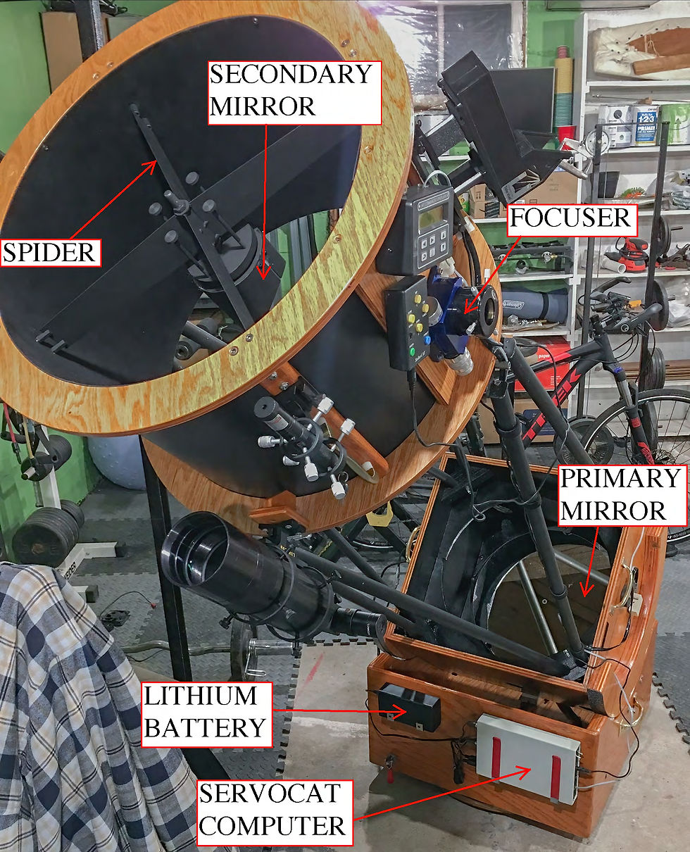
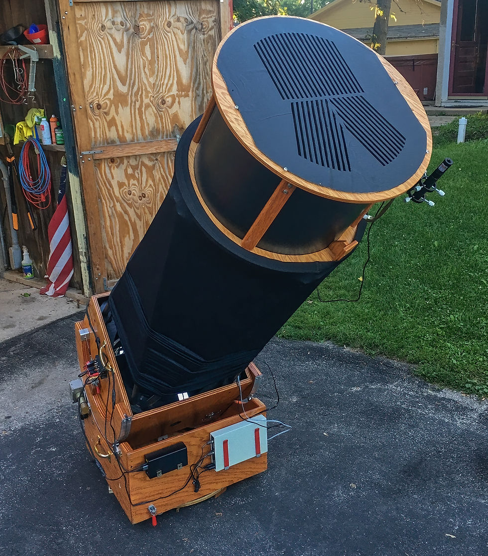
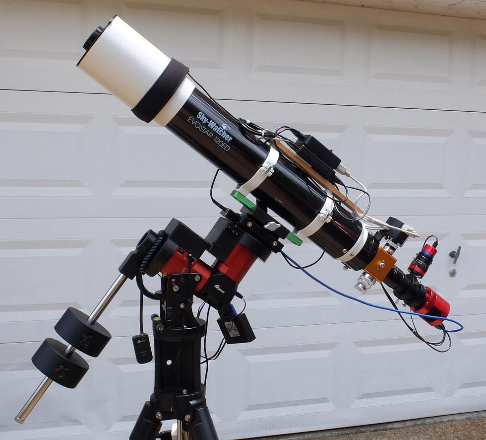
My telescope is a basic truss tube style Dobsonian scope that’s constructed mostly of plywood with a few specialized metal components and electronics. As with all Dobsonians, the optical design is that of a Newtonian reflector consisting of two mirrors. The primary mirror is concave and sits at the bottom end of the telescope, closest to the ground. This mirror is just slightly smaller in diameter than the tube of the telescope itself. Mine has a diameter of 17.5 inches. The second mirror is much smaller and sits near the sky end of the telescope, suspended in the middle of the tube by a thin metal structure known as a spider. This mirror, called the secondary mirror, sits tilted at a 45-degree angle to the axis of the telescope tube. Light enters the end of the telescope tube and bends, or diffracts, slightly around the metal vanes of the spider. This diffraction is actually what causes the plus-shaped spikes on the brighter stars in my images.
The light then continues down the tube, hitting the primary mirror at the bottom of the tube. Because that mirror has a concave surface, it reflects the light back up the inside of the tube, into a cone shape. The thin end of the cone then bounces off the secondary mirror and out the side of the scope, through the focuser, into either an eyepiece or a camera.

Where the cone of light comes to a point, is called the focal point of the telescope. The distance between the focal point and the surface of the primary mirror is called the focal length. My scope has a focal length of 2000mm. Typical focal lengths of regular DSLR camera lenses are in the 10-600mm range, for comparison. The telescope’s focuser is used to move the camera or eyepiece in and out until the focal point of the light cone hits either my eye or the sensor of the camera. That’s the basic optical design of all Dobsonian scopes, though many smaller and mass-produced scopes use a solid metal tube design instead of the two-piece truss tube design mine employs.
The primary mirror is held in place and evenly supported by a metal structure called the mirror cell. The cell evenly supports the back and bottom edge of the mirror to prevent stressing the glass, which can affect the images the scope produces. The mirror cell also has three adjustment bolts on the back that are used to point the primary mirror and align it with the secondary mirror, in a process known as collimation. Additionally, the mirror cell houses a fan that blows air onto the back of the mirror.
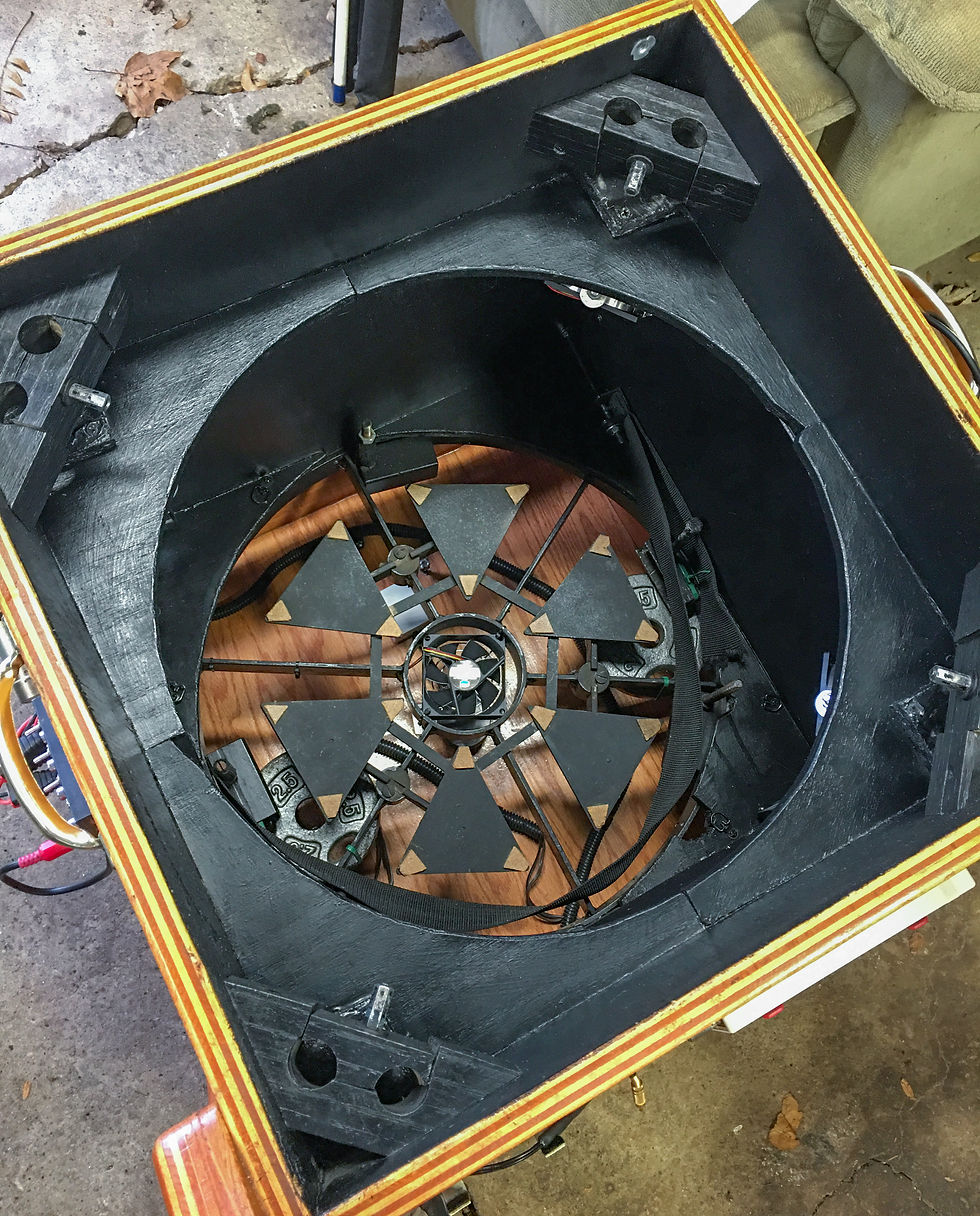
The fan, along with others mounted nearby, acts to cool the 2" thick primary mirror and prevent air currents of differing temperatures inside the telescope tube, which will degrade the image, since light refracts slightly when moving through air of differing temperatures. This is the same reason why you can see miragey-looking wavy images over hot pavement. Only in this case, the pavement is a thick piece of glass that has soaked up heat during the daytime and can't cool fast enough to match the falling nighttime temperatures.
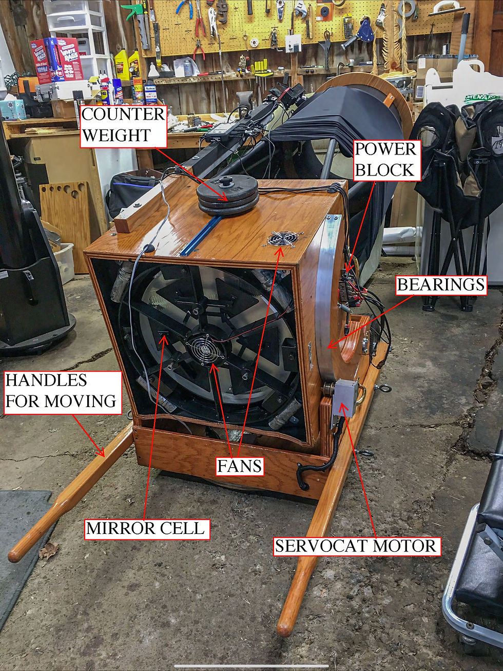
The primary mirror and its cell are housed in a plywood box, called the mirror box. The mirror box has wooden, half-circle shaped bearings with strips of steel on the bottom side that are used to rock it back and forth inside of the bottom structure, called the rocker box. This rocking motion adjusts the up and down, or altitude, axis of the scope.
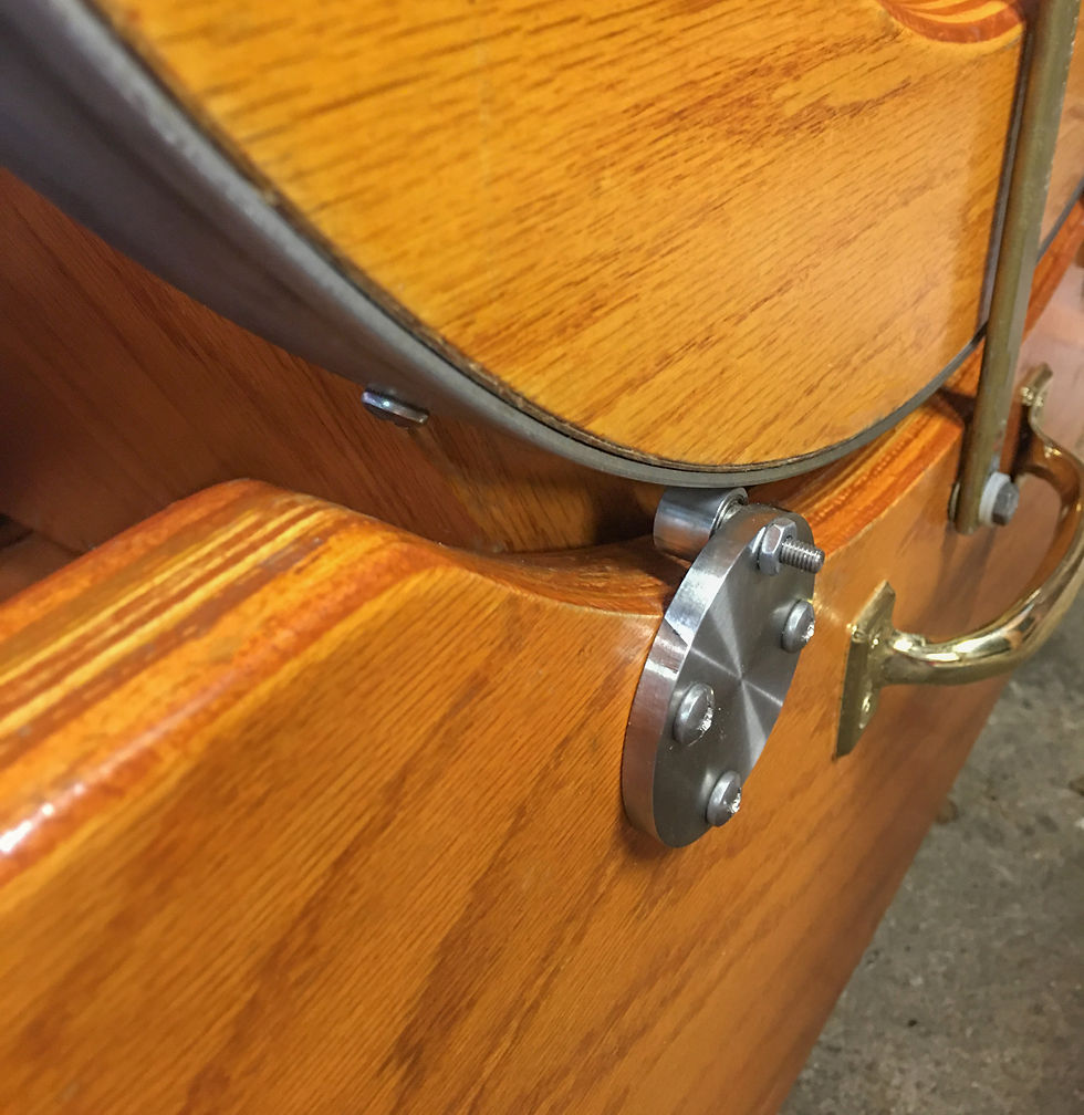
At first, I used aluminum strips on the bottom of the bearings, which are visible in some of the pictures. The aluminum strips turned out to be too soft, so I replaced them with 1/8" thick strips of steel, shown here. The side-to-side, or azimuth, motion is facilitated by a 20" heavy-duty lazy susan bearing in the bottom of the rocker box. In order to allow smoother tracking of objects when I image, I installed 4 roller bearings on the rocker box, which I had custom made by a local machine shop. The steel strips on the bottom of the mirror box bearings ride on these 4 roller bearings and produce a very smooth, low-friction motion. This has helped immensely with the 10-20 second long exposures I use when imaging.
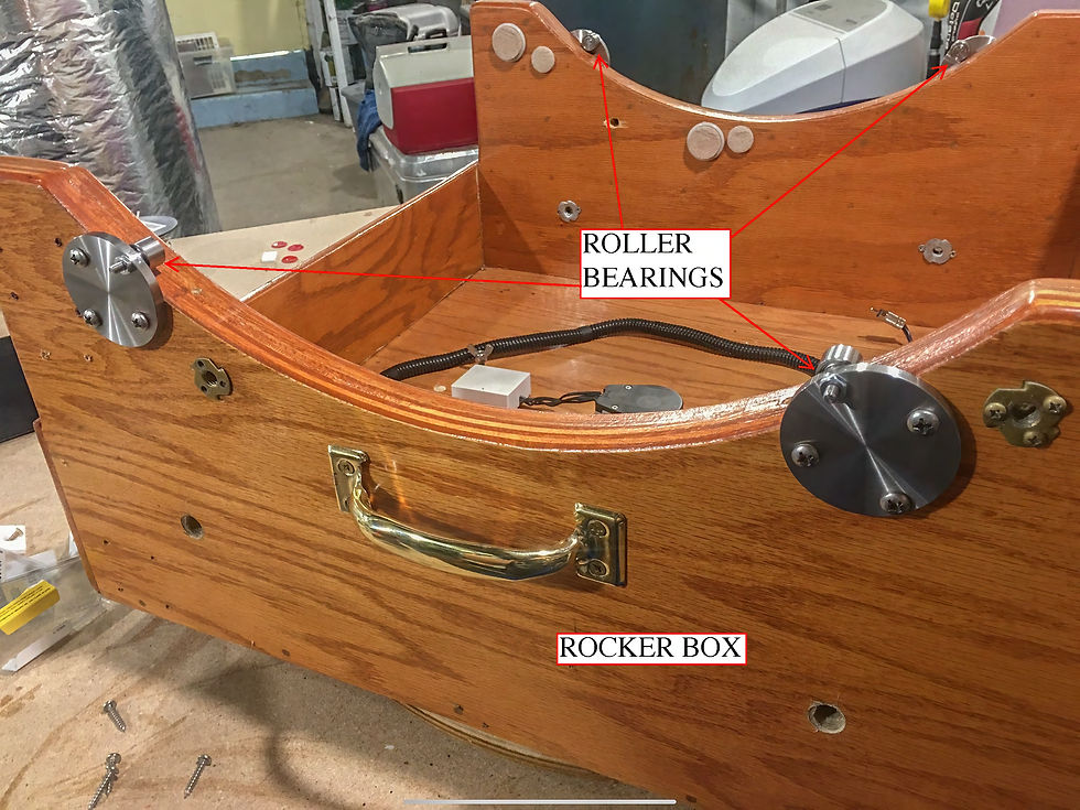
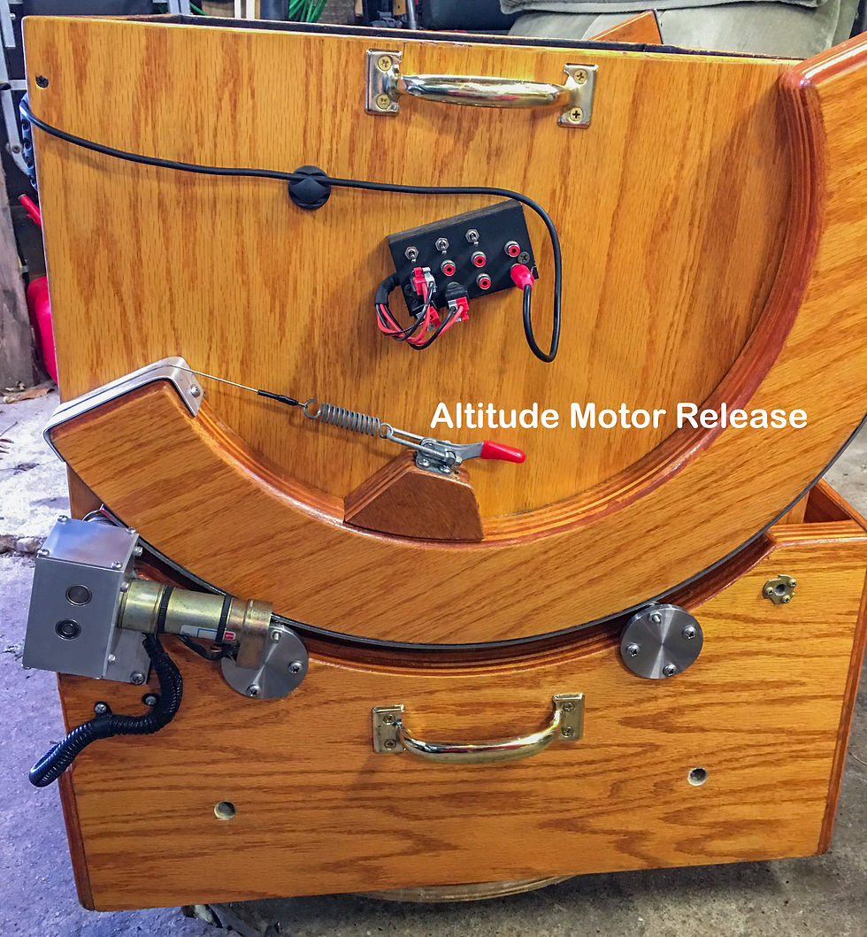
The rocker box also houses the scope’s ServoCat system, which consists of two motors and a computer box to control them. One motor controls the scope’s altitude motion via a steel cable that wraps around one of the wooden bearings on the mirror box and the other motor controls the azimuth motion using a metal shaft that rides along a circular piece of plywood on the bottom of the scope called the ground board. Each motor has a lever associated with it to engage and disengage the motors, allowing the scope to be moved around by hand. The rocker box also holds the lithium battery pack that powers the motors and all of the other electronics on the scope.
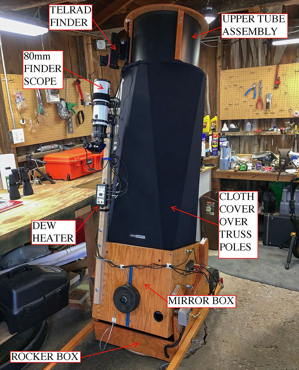
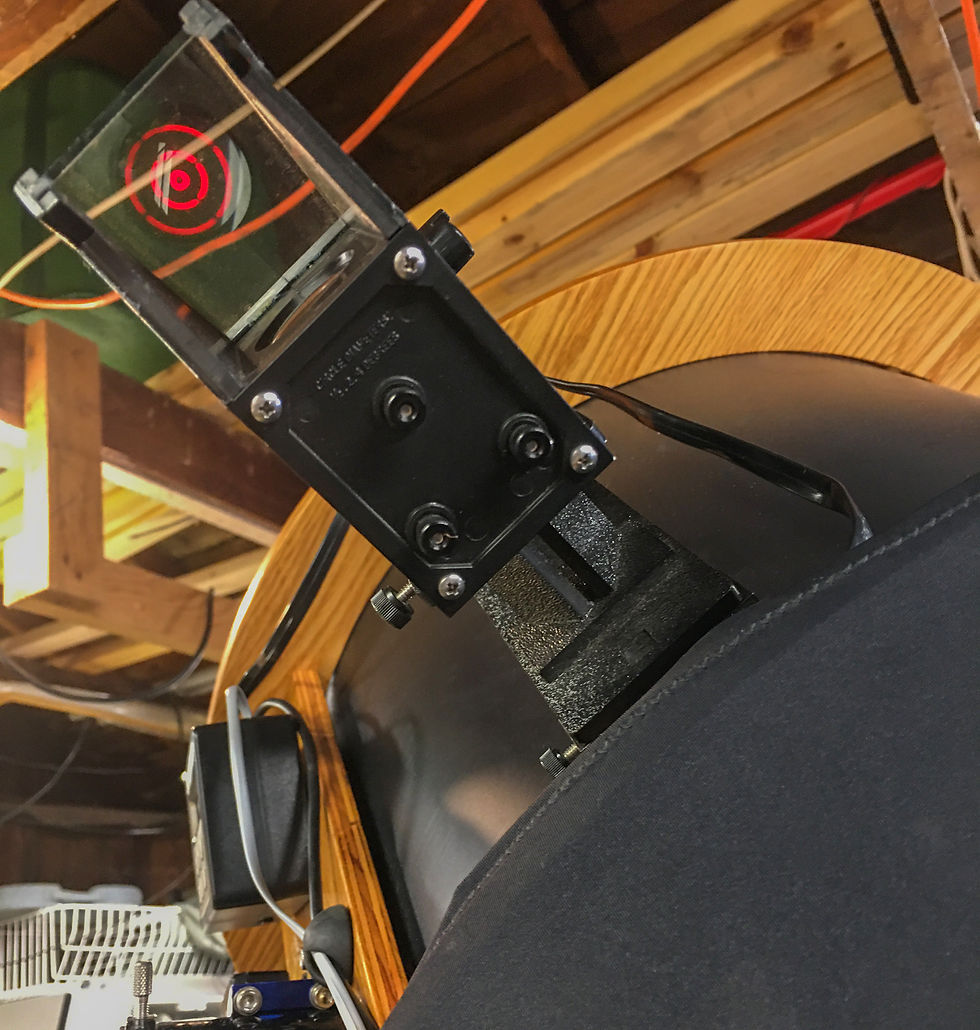
Next is the upper tube assembly or UTA. This is the upper part of the telescope tube and it's attached to the mirror box via 8 aluminum truss poles. It houses the spider and the secondary mirror, along with the focuser and various tools for aiming the telescope. On my scope, these tools include a powerful green laser pointer and a Telrad finder, which basically functions like red dot optics for firearms. The red circles shown in the Telrad display are .5, 2, and 4 degrees across, which helps when navigating the stars.
I also sometimes use a smaller finder scope to help aim the big scope if I'm hunting for dimmer objects. It's an 80mm short tube refractor that mounts to the mirror box using a 2"x 2" piece of oak. On nights with high humidity and rapidly dropping temperatures, condensation can form on many surfaces of the telescope, including the secondary mirror, the finderscope, and the eyepiece (if using visually). Because of this, I sometimes need to use a dew heater, which applies a small amount of heat on whichever surfaces I'm trying to prevent condensation. The dew heater also mounts to the oak board and runs off of the same lithium battery pack as all the other electronics on the scope.
Other Gear
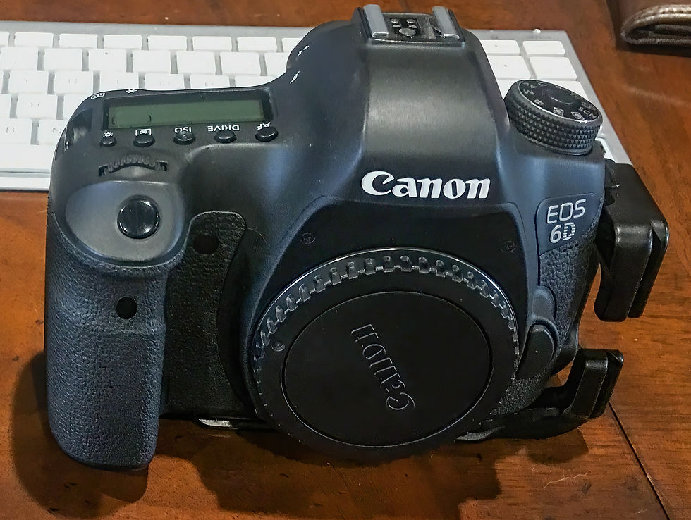
There are a few other important pieces of gear I use for imaging. The most obvious would be my camera, which is a Canon 6D full-frame DSLR. Although it's a slightly older model, the 6D has been a great choice for my needs so far. It performs well in low light conditions, has large pixels that pair well with my scope's long focal length, and can often be found for cheap on the used market. I think I paid $500 for mine.
It's possible to modify a DSLR camera to become more sensitive to certain wavelengths of light, such as those that come from the ionized hydrogen gas commonly found in deep sky objects. This involves removing one or both of the infrared/ultraviolet filters, which normally cover the camera sensor. Human eyes don't detect infrared light, so for normal daytime photography, you don't want the camera to detect it either. By removing the filters, the camera becomes much more sensitive to deep red and infrared light and would then provide more detail and red colors in those objects that contain strong hydrogen signals. I've recently acquired a second Canon 6D, which has undergone a modification to remove one of the IR/UV filters. I will post my results and a comparison as soon as I get the chance to test it out.
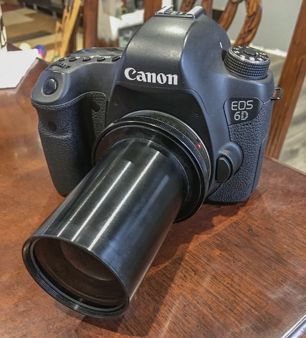
Another important object I use is the coma corrector, which attaches to the front of my camera like a lens. Coma is an optical aberration inherent to all newtonian reflecting telescopes and, therefore, all Dobsonians. It has to do with the parabolic, concave shape of the primary mirror itself. When looking through the eyepiece or taking a picture without a coma corrector, stars at the center of the frame will look normal, but stars on the outer edges of the frame will appear comet-shaped, having a slight tail extending from the star outward.

The effect will be more pronounced the further from center you move, and "faster" telescopes (those with a lower f stop value) will show it more. Many astronomers start to notice coma visually around f5 or f6. Since my scope is f4.5, it is quite noticeable, especially when imaging. A coma corrector is an extra optical component that sits between the telescope and the camera and corrects this issue before the light reaches the sensor.

The result is a nice flat field with pin point stars across the entire frame. There are a few different coma correctors out there, but I use the Televue Paracorr II since I already owned one for visual use before I got into astrophotography. Converting the Paracorr II for use with my camera required an adapter (Televue part no. CWT-2070), which has the standard Canon bayonet mount on one side and is threaded on the other side to accept the optical tube of the Paracorr. There is a different part number for the Nikon version of this adapter. The tuneable top of the Paracorr, which is for visual use, can be unscrewed from the optical tube and is not required when imaging.
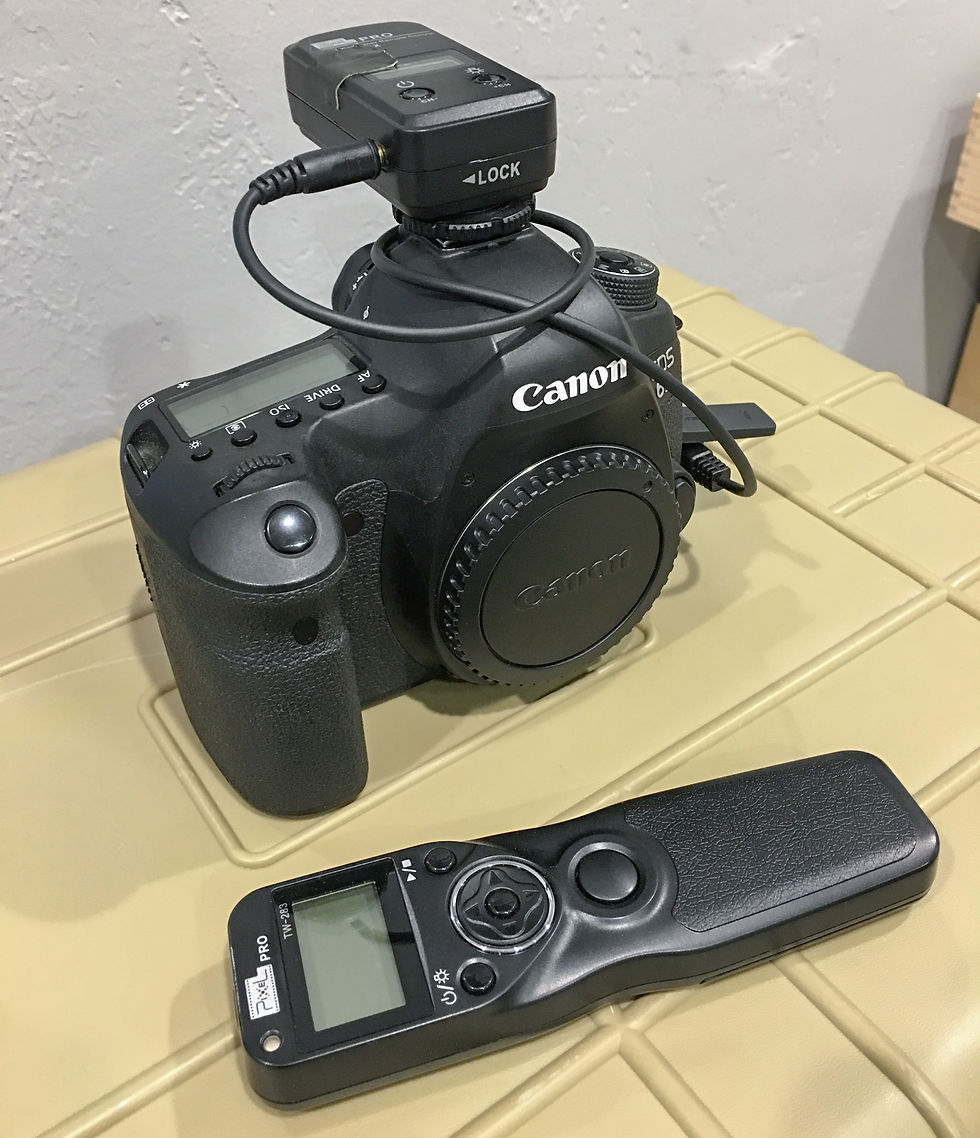
An intervalometer is another very useful piece of gear for DSLR astrophotography with a Dobsonian. It allows me to snap a photo without touching my camera, which would undoubtedly shake the telescope and ruin the photo. The intervalometer can also automate the entire process so I can walk away from the telescope while it continues taking photos. It consists of a small device that sits in the camera's hot shoe and a remote control that communicates with it. Using the remote control, I can program the intervalometer to take a series of photos in any way that I'd like. For example, I might tell it to take 200 photos, each 10 seconds long, with 4 seconds between each photo. I push the button to run the program and then I can walk away while the camera takes that exact sequence of photos. This is a huge improvement over taking a single photo at a time using your phone or a remote shutter.
The last item I'd consider important is the bahtinov mask. One problem I faced when I started imaging was how to focus the camera after I had the object I wanted to image centered in the frame of the telescope. When focusing a telescope for visual use, you simply use your eye to tell when the target becomes the sharpest. After the camera is inserted in the focuser though, you can no longer see the object to do this. The exception would be if you're imaging something bright like the moon or a planet. In those cases, you can usually see the target enough to focus on it using the camera screen. But with very faint deep sky objects, it's not so easy. It's possible to try focusing on a bright star using the camera screen, but there will be quite a wide range where the star looks focused, even though the focuser is being moved in and out slightly.
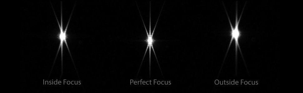
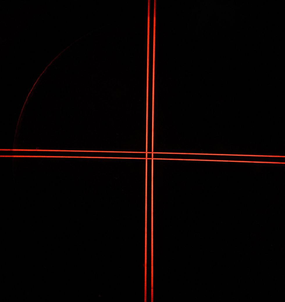
A great solution to this problem is the Bahtinov Mask. This special shield goes over the end of the telescope when it comes time to precisely focus the camera, usually right before I start imaging. These can be purchased for various sizes of smaller telescopes, but I had to custom make mine because I couldn't find one large enough online. I cut my mask out of rigid cardboard using a vinyl pattern that my wife made with her Cricut cutting machine. Then I spray painted both sides flat black. To use this tool, I point the telescope at a brighter star and put the mask over the end of the telescope. I then zoom all the way in to 10x using the camera's digital zoom. The pattern of the cutouts in the mask makes the star show up on the camera screen with 6 large diffraction spikes (when the camera is moved close to focus). The image here shows what the diffraction spikes will look like when the telescope is in exact perfect focus.
My Imaging Methods
Here I will lay out the actual steps I use when imaging a deep sky object. Mind you, this is only half of the process that goes into creating deep sky images. I always think of astrophotography as both a science and an art. The actual imaging side of the process is the science, where the goal is to collect the best data possible with the gear available to you. If you've gathered lots of good data, then the image processing step, which I consider to be the art side of astrophotography, will go much smoother. But what do I mean by "good data?"
The main struggle with deep sky astrophotography is how dim most of the targets are. To combat this, astrophotographers take very long exposures with their cameras, where the shutter remains open and collecting the actual photons that left the object long ago, for usually several minutes, in order to produce a single photo. Many of these long exposure photos are then stacked on top of each other (to increase the signal to noise ratio) and processed with photo editing software to produce the final image. Exposures of several minutes require that the telescope stay perfectly centered on the target object the entire time. Otherwise, the stars in the photo will appear streaked across the frame in the direction of motion. The image below is a single 10 second photo of The Orion Nebula (M42) straight off my camera with no stacking or processing. The stars in the photo are streaked and probably resulted from poor alignment or me accidentally bumping the scope.

Keeping the target perfectly centered can be quite difficult since all objects in the night sky appear to move as the Earth rotates. The vast majority of astrophotographers out there use German Equatorial Mounts (GEMs) to accomplish this, which are designed to track the motion of the Earth very precisely. But the scopes that most GEMs can carry accurately, are quite small in diameter compared to a larger Dobsonian like mine. With a small telescope in the 50-150mm diameter range, exposures of 1-3 minutes or longer are common (and usually required) to obtain enough signal for a usable image.
My Dobsonian scope can only track accurately for about 10-20 seconds, though. Any more and the small perpendicular motions of the alt/az tracking will create streaked stars. Luckily, that is enough for many deep sky objects, since the diameter (or aperture) of my scope is 17.5 inches (444mm).
This is not a common way of imaging, but I've found that it can indeed be done. It's taken me a long time to tweak the process and figure out what works best for my equipment. I'd like to share what I've learned so far in hopes that it might save somebody else the time and hassle it's taken me to figure out. I'll try to be specific enough so that someone unfamiliar with astrophotography techniques can still follow along and understand the process. I've broken it down into 10 basic steps.
Cool primary mirror and check collimation
Roughly balance the scope using its counterweight
Perform alignment using the Sky Commander DSC unit
Test alignment and calibrate if needed
Slew to bright star and center in frame
Use Bahtinov mask to precisely focus the telescope
Remove Bahtinov mask
Slew to target object
Center target in frame of camera
Double check camera settings and begin imaging
Cool primary mirror and check collimation
As I mentioned above, it's important to cool down the primary mirror of a Dobsonian before using it. If you don't, the heat that the thick mirror has absorbed during the daytime can cause air currents of differing temperatures inside the tube of the scope as the nighttime temps start to drop quickly after dark. Fans are one of the best ways to combat this and some scopes even come with them already installed. Fans can also be bought and installed after purchasing if your scope doesn't have one. My scope has a total of 7 fans that all run off the lithium battery pack. One blows directly on the back of the mirror, which is the most common fan placement. I also have two fans mounted in the side of the mirror box blowing on the edge of the mirror, that are designed to circulate air throughout the mirror box.
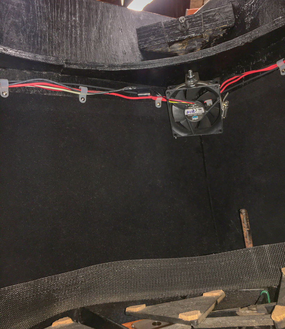
Then there are 4 fans mounted to the inside corners of the mirror box and blow air directly onto the front surface of the mirror at a low velocity. Those 4 stay on even while imaging, but the rear and side fans introduce too much vibration into the scope and they get turned off once I start the imaging process. On a night when I know I'll be imaging, I usually go out an hour or two before sunset to turn the fans on and get the mirror cooled down. I leave my scope fully assembled in my unheated garage so all this task consists of is flipping a couple switches on the powerboard that everything plugs into. At this point, I usually pull the scope out into the driveway using wheelbarrow handles that screw onto the side of the rocker box.
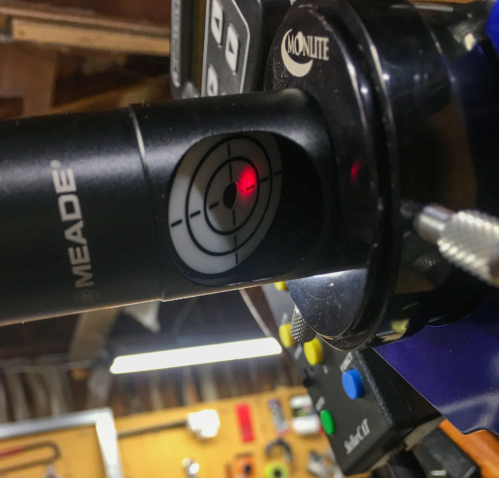
I also take this time to check the collimation of the scope. This insures that the two mirrors are property lined up with each other and the scope gathers the maximum amount of light it can. There are several different tools that can be used to help with collimation but I use a laser device made by Meade. There are more accurate tools out there, but I haven't had any issues with this one so far. To use it, I rack the focuser on the scope all the way out and insert the laser into the 1.25" adapter. Then, I turn the laser pointer on low and check that the dot from it is hitting the center mark on the primary mirror. It's difficult to take photos of this so I labeled the picture below.
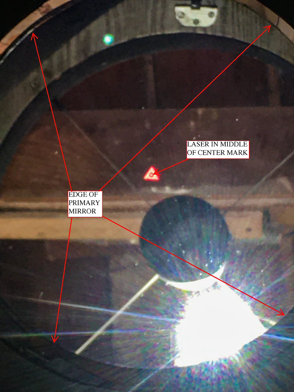
If the laser isn't centered, I use the adjustment screws on the back of the secondary mirror to move the spot that the laser hits the primary mirror until it's centered on the triangle-shaped center mark of the mirror. Next, I look at the inside of the laser tool, where there is small target with a hole in the middle. The laser light leaves through the center hole and bounces off the secondary mirror towards the primary mirror. After hitting the center mark on the primary mirror, it bounces straight back where it came from, first hitting the secondary mirror again and then the target on the inside of the laser tool. The goal is to use the 3 adjustment bolts on the back of the primary mirror cell to shift the laser dot around on the target until it's lined up directly with the hole at the center of the target, where the laser originally came from.
At that point, the telescope's two mirrors are lined up with each other and collimation is complete. A reflecting telescope will typically hold collimation for a while if it isn't being moved around a lot. Since I move mine back and forth from the garage often, I usually check it before I start imaging. Collimation is extremely important for newtonian reflecting telescopes and will cause many problems when imaging, if not performed correctly.
Roughly balance the scope using its counterweight
The next thing I do is slide the counterweight around on the back of the mirror box until the scope is evenly balanced when pointed at the approximate altitude of the object that I'm attempting to image. If I grab the sky end of the telescope tube and slowly move it up and down, I should feel equal resistance in both directions.
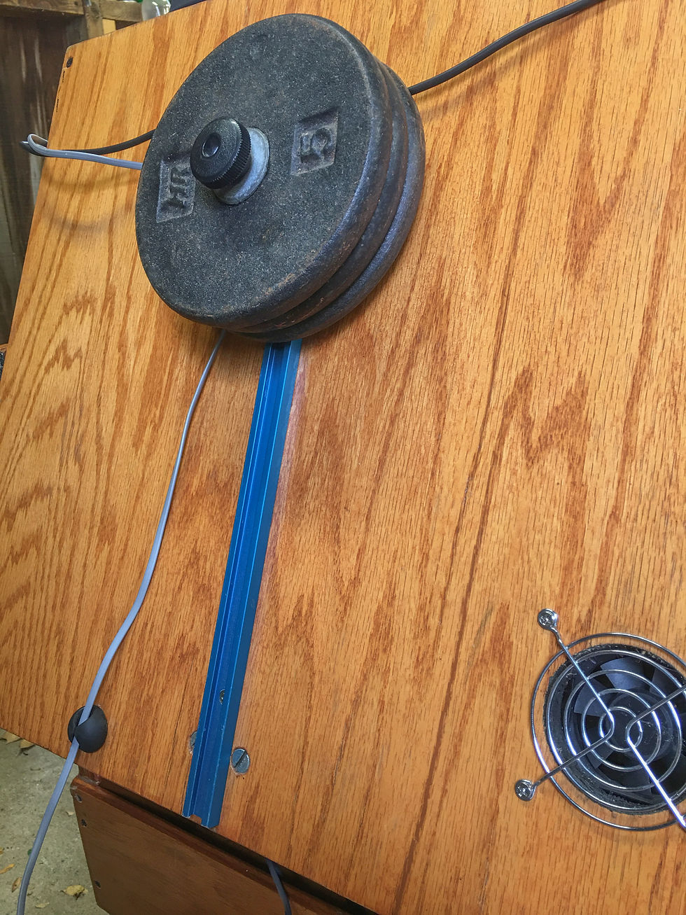
This helps to insure that only a small amount of force is needed to move the scope in any direction, which will help with tracking while the scope is imaging. My counterweight system was a custom addition, like many other components on my scope. It consists of an aluminum track, like those designed for accessories on kayaks, along with 15 lbs. of 1 inch barbell weights. To slide it around, I simply loosen the plastic knob on top. I realize this won't be an option for most mass produced scopes, but I've seen some people use magnetic welders weights as counterweights on metal tube Dobsonians so that might work well for some.
Perform alignment using the Sky Commander DSC unit
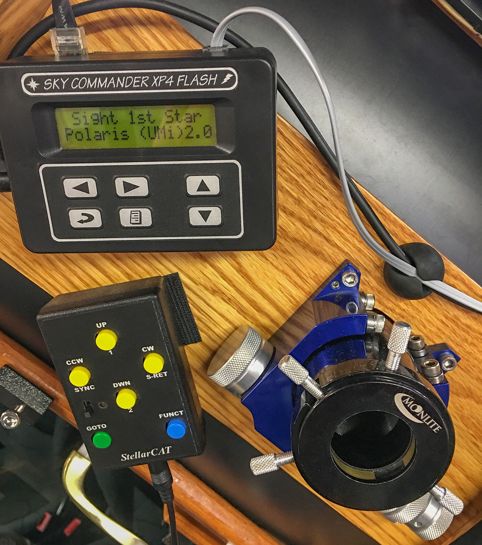
The next step is to perform an alignment with the scope so it learns what it's pointing at. The scope has two devices that sense rotation, called encoders. One of them sits right on the center of the altitude bearing and the other sits right on the center of the azimuth bearing. These two together can sense any motion the scope makes, whether it's up and down or side-to-side. Both encoders are hooked up to a small computer unit called a Sky Commander XP4. Together with the Sky Commander, they make up what's called a Digital Setting Circles system (DSC). This system uses two points in the sky to create a virtual map of hundreds of different objects, which are stored in the computer.
First, I insert a special eyepiece into the focuser of the scope. This eyepiece is high magnification and has an illuminated crosshair reticle that can be used to perfectly center the telescope on a star. To begin the alignment, I turn on the Sky Commander unit and enter the date. It then asks me to select the first of two alignment stars that I'm going use. It defaults to Polaris (the north star) as the first option and that's usually what I use. I manually push the scope over to Polaris and center it.
I should also mention at this point that I had to design a special device on my scope to add some friction to the side-to-side (azimuth) motion because it was too loose to properly line up a star or view by hand. This device just consists of a flat bottom bolt with adhesive felt stuck to it, which threads into the bottom of the rocker box and rubs against the ground board when tightened. Before starting the alignment, I tighten this bolt to put a little pressure against the ground board and make alignment easier.
Once Polaris is centered in the eyepiece, I push enter on the Sky Commander and then it asks me to select the second star. I'm always careful to very precisely center the alignment stars and make sure I don't bump the scope while pushing enter. At this point I look for a brighter star on the opposite side of the sky that's between about 10 and 60 degrees in altitude. If I don't know the name of the star, I use an augmented reality app on my phone called Skyview, that shows the night sky as you point the phone around in all directions. After lining up the second star and hitting enter, the Sky Commander unit knows where the scope is pointing at all times. Since there's a cable connecting the Sky Commander computer with the ServoCat computer for the motors, all that's left to do is flip the two red levers that engage the motors.

Up until this point, the motors had been disengaged so I could move the scope around by hand. Once the two motors are engaged, the scope can no longer be moved by hand and is fully controlled by the computer, motors, and the remote pad. At this stage, I also loosen the bolt that I used to put tension against the ground board so there's as little friction as possible.
Test alignment and calibrate if needed
After performing the alignment, I usually select a bright and familiar object in the Sky Commander database and tell the scope to point at it. The scope will swing around all on its own and attempt to center the object in the frame. It's usually surprisingly accurate on the first try as long as I was very careful when centering the alignment stars. Most of the time, at least part of the object will be in frame without any adjustment needed. If the goto happens to miss slightly, though, I can use the remote pad to slowly move the scope around manually until I find the target object in the eyepiece. Then, I can use the "recenter on object" command in the menu of the Sky Commander unit to correct the slight mistake in the alignment. This will help ensure the tracking is more accurate during imaging.
Slew to a bright star and center in frame
Once I know the alignment is correct, I remove the crosshair reticle from the focuser and insert the camera with the coma corrector attached. I use the remote pad to slew the telescope over to a bright star and center it.
Use Bahtinov Mask to precisely focus the telescope
At this point, I place the Bahtinov mask over the end of the scope. I use the digital zoom on the camera screen live view to zoom in all the way on the star. Then I move the focuser in and out until the diffraction spikes created by the Bahtinov mask match the image I showed above.
Remove Bahtinov mask
This may seem like an obvious next move, but I felt it was important enough to warrant its own step. On several occasions, I've spent an hour imaging only to realize that I forgot to take the mask back off after focusing. It sucks going through all the hassle of setting up only to ruin some of your images by forgetting something so simple.
Slew to target object
Now I can finally swing the scope over to the object that I intend to image. I select it in the Sky Commander unit and press "goto" on the remote pad. The scope moves to the object and begins tracking it. At this point, I can no longer see through the scope to see if an object is centered or not. The easiest way I've found to make sure my target is centered in frame before I begin imaging is to crank up the ISO/sensitivity on my camera all the way and take a 10 or 15 second image. The scope is large enough where I can usually make out most of my targets with these quick and dirty snapshots. I can then use the remote pad to move the scope around slowly while taking these photos until the target object is perfectly centered in frame. I will sometimes carefully rotate the camera in the focuser at this point if I need to turn the subject in the frame to make it fit better.
Double check camera settings and begin imaging
Once I know the subject is centered in frame, I adjust my camera settings to the values I want to use on that object. I typically shoot in full manual mode at ISO 3200 and set the camera to take RAW photos instead of JPEG format photos. The RAW file format is preferred by most photographers and contains only the actual values of color and brightness that each pixel on the camera sensor captured during the exposure. It holds more details and allows much greater control during the image processing stage. JPEG images, on the other hand, are compressed and edited by the camera itself. They don't contain as much information and tend to be several times smaller than RAW images taken with the same camera. I always recommend shooting in RAW mode to preserve details and flexibility when editing.
The ISO 3200 value has ended up being a great balance of high sensitivity and low noise for my short exposures. Generally, the higher you crank up the ISO value, the noisier and more grainy the image will be. On most targets I've imaged so far, I've used 10 second exposures. If I'm imaging a dimmer target, I might increase that to 15 or 20 seconds, which allows more light signal to be collected in each individual exposure. This will usually result in more frames needing to be tossed out, though (due to streaked stars), when compared to using 10 second frames. Settings such as ISO and exposure time are things that I'm continually experimenting with to see what works best. With the addition of my new modified camera, I should be able to pick up much more red signal in my 10 second exposures.
Upon completing all the steps above, I'm ready to start imaging. I program the intervalometer to take a couple hundred pictures in a row, all 10 seconds long, and walk away. About every 15 or 20 minutes, I'll come back to check on the camera and make sure that the target is still in the middle of the frame. If it slowly drifted while I was away, I use the slow motion controls on the handpad to re-center and continue taking photos. After several hours of this, I'll be left with hundreds of individual photos on the camera's memory card. The next step is to sort through them on the computer and delete the ones that didn't turn out well. This could be due to poor tracking, bumping the telescope, or other issues such as a satellite streaking across the frame in the middle of an exposure.
After getting rid of the bad photos, I'm ready to stack all the individual frames together to create a single image, which can then be processed using photo editing software, such as Photoshop or Pixinsight. During the stacking step, the individual frames are also combined with various types of calibration frames, designed to eliminate extra signals that the camera sensor picked up. These signals could come from various sources such as hot pixels in the camera sensor, specs of dust on the camera or lens, light pollution in the sky around the target, or simply the read noise that the camera produces any time it reads the raw data from the sensor and converts it to an image file. Either way, we are only interested in the signal from the target object so we want to correct for the other sources. Stay tuned for a future article explaining the stacking process and each of the calibration frames commonly used in astrophotography.

Comments